Bed Installation
- Carefully lay out the system components and define setbacks from wells, property boundaries and land forms such as streams and drainage ways in accordance with state and local regulations.
- Prepare the site according to, and following all state and local regulations. Do not install a system on frozen ground, saturated ground, or wet soils that are smeared during excavation. Keep heavy machinery off clayey soils used for the GSF system as well as down-slope from the system where soil structure is critical for absorption and drainage of the treated effluent.
- Plan the diversion of upslope stormwater. Set soil grades at 3% minimum to ensure that stormwater drainage is diverted away from the GSF system area once the system is complete.
- Excavate the bed. Scarify the receiving layer to maximize the interface between the native soil and the ASTM C33 specified sand layer.
- Remove all organic soil and roots at disposal and fill extension areas.
- Minimize walking in the trench or bed prior to placement of the ASTM C33 specified sand to avoid soil compaction.
- Based on the GSF approval in your state, place the proper amount of a specified ASTM C33 sand with less than 10% passing a #100 sieve and less than 5% passing a #200 sieve and with a Coefficient of Permeability greater than 5 feet per day on the bottom of the excavated bed.
- A hand tamper is sufficient to stabilize the sand below the GSF modules. Set the elevation of the top of the ASTM C33 specified sand and check to make sure it is level using a 2” x 4” board and a carpenter’s level, or a laser level before placing the GSF modules.
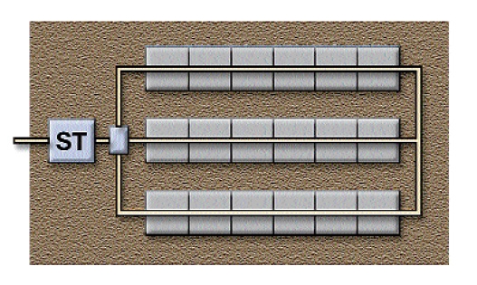
- Avoiding footprints, place GSF modules with PAINTED STRIPE FACING UP, end to end on the ASTM C33 specified sand layer in the bottom of the bed. The distance between module rows is 12” minimum and can vary based on the Eljen approval from the state or local issuing authority. CAUTION: Spacer cores can have sharp edges.
- Provide distribution box(s) or drop-boxes depending if the site is level or sloped.
- Use 4” SDR 35 non-perforated pipe from the distribution box to the perforated pipe that is installed above the GSF modules. Note: perforated pipe is only used above the modules.
- Center 4” SDR 35 perforated distribution pipe lengthwise over modules with orifices at 5:00 and 7:00. In level systems, connect distribution lines using non-perforated pipe at the distal (far) end of the system, and at the mid-point of the system in systems that are over 40’ in length.
- Secure the distribution pipe to GSF modules using one Eljen wire clamp per module. Push clamp ends straight down into up-facing core, through the fabric, and into the underlying ASTM C33 specified sand layer.
- Spread Eljen cover fabric lengthwise over the pipe and drape over the sides of the GSF module rows. Secure the fabric by placing several shovels of specified sand on top of the modules, between and along the sides of the modules. Avoid blocking holes in perforated pipe by placing the cover fabric over the pipe prior to placing fill over the modules.
- Based on the GSF approval in your state, place the proper amount of the specified ASTM C33 sand between module rows (12” minimum), and along the sides and ends of modules in the bed.
- Complete backfill using excess ASTM C33 sand on top of the modules then loam to 12″ minimum over the entire GSF system. Backfill should be clean, porous and devoid of large rocks. Backfill exceeding 18” requires venting at the distal (far) end of the bed. Do not use wheeled equipment over system. A light track machine may be used with caution, avoiding crushing or shifting of pipe assembly. Backfill in direction of perforated pipe.
- Final grading of the site shall be in accordance with state and local regulations. Set grade of system and upslope area to divert stormwater runoff. Finish grade over the GSF system shall be at a 3% minimum to prevent surface ponding. Backfill material surface shall be stabilized by seeding or sodding to establish a good vegetative cover to prevent erosion.